
I recently decided to repurpose a recovered Graw DFM-17 radiosonde as a 70-centimeter amateur-radio tracker for our 2026 Jamboree on the Air high-altitude balloon project. On paper, this looked straightforward: solder in a programming header, connect an ST-LINK, build RS41ng, and flash it.
In reality, the project involved a reversed ribbon-cable orientation, a browser flasher that could not communicate with the ST-LINK, Windows-to-WSL USB forwarding, an apparently correct reset circuit that still could not establish an SWD session, and a final manual-reset maneuver that opened the door.
The result was worth it: the DFM-17 was mass-erased, programmed with a custom Horus Binary V3 configuration, verified byte-for-byte, and heard transmitting on 432.501 MHz as KN4OLA-12.
Important warning: This process permanently erases the factory firmware once the mass-erase operation succeeds. It also involves transmitting on amateur-radio frequencies. Confirm your wiring, preserve your configuration files, attach a suitable antenna before transmitting, and operate only under the privileges and requirements of your amateur-radio license.
What Is the Graw DFM-17?
The DFM-17 is a meteorological radiosonde originally designed to measure atmospheric conditions while suspended beneath a weather balloon. The recovered unit used in this project contains:
- An STMicroelectronics STM32F100 microcontroller
- A u-blox MAX-M8C GNSS receiver
- A Silicon Labs Si4063 UHF transmitter
- An onboard battery supply, power-control circuit, LEDs, and antenna connection
Those components make the DFM-17 an excellent candidate for reuse. RS41ng replaces the original meteorological firmware with an open-source amateur-radio firmware supporting modes including Horus Binary V3, APRS, CATS, CW, and other experimental functions.
Parts and Tools
I used the following hardware:
- Recovered Graw DFM-17 radiosonde
- Adafruit 4048 “Skinny” 1.27 mm 2×5 SMT SWD header
- Adafruit 1675 10-pin 2×5 socket ribbon cable
- Adafruit 2743 2×5 1.27 mm SWD breakout board
- Adafruit 2548 ST-LINK V2-compatible programmer
- Four jumper wires
- Weller WLC100 soldering station
- Klein CL700 multimeter
- Windows computer with WSL/Ubuntu
The multimeter was not optional. Photographs and keyed connectors can suggest an orientation, but continuity testing tells the truth.
Soldering the Programming Header
The DFM-17 exposes its programming interface as an unpopulated 2×5 group of 1.27 mm pads between the sensor-boom connector and the STM32. I soldered the Adafruit 4048 header directly to those pads.
For fine-pitch work, I used a clean, properly tinned tip, flux, a small amount of solder, and magnification. The useful technique was to anchor one corner, verify alignment, secure the opposite corner, and only then solder the remaining pins. More solder is not better; a clean fillet and no bridges are the goal.
The DFM-17 SWD Pinout
With the sensor-boom connector on the left and the STM32 on the right, RS41ng documents the programming connector as follows:
| DFM-17 pin | Signal | Used here |
|---|---|---|
| 1 | VTRef / optional 3.3 V supply | No—batteries powered the sonde |
| 2 | SWDIO / TMS | Yes |
| 3 | Ground | No |
| 4 | SWCLK / TCK | Yes |
| 5 | Ground | Yes |
| 6 | SWO / TDO | No |
| 7 | Key | No |
| 8 | NC / TDI | No |
| 9 | Ground detect | No |
| 10 | nRESET | Yes |
My final four-wire assignment was:
| Wire color | Breakout label | ST-LINK label | DFM-17 pin |
|---|---|---|---|
| White | SWIO | SWDIO | 2 |
| Brown | CLK | SWCLK | 4 |
| Black | GND, third position on the left | GND | 5 |
| Red | !RST | RST | 10 |
I powered the DFM-17 from its batteries and did not connect the ST-LINK 3.3 V output. Do not connect two competing power sources unless you have verified that the programmer’s VTRef implementation is truly sense-only. Many inexpensive ST-LINK-compatible dongles expose a 3.3 V output rather than a separate target-voltage reference input.
The Ribbon-Cable Orientation Trap
I initially matched the available photographs exactly. Continuity testing then revealed that breakout SWDIO was landing on DFM-17 pin 9—not pin 2. The entire ribbon mapping was reversed:
1 ↔ 10
2 ↔ 9
3 ↔ 8
4 ↔ 7
5 ↔ 6
Flipping the ribbon cable corrected the mapping without desoldering the header. This was the first major lesson of the project:
Do not trust connector keys, cable stripes, product photographs, or assumptions about pin 1. Verify every required signal electrically from the programmer side to the target.
End-to-End Continuity Verification
Before attempting another connection, I verified the complete signal paths to the STM32 itself. With all power removed and the STM32’s pin-1 marker oriented at the upper-left:
| Signal | STM32 pin | Physical location |
|---|---|---|
| SWDIO | PA13, pin 46 | Right edge, third lead down from upper-right |
| Ground | VSS, pin 47 | Right edge, second lead down from upper-right |
| SWCLK | PA14, pin 49 | Top edge, rightmost lead |
| nRESET | NRST, pin 7 | Left edge, seventh lead down from upper-left |
All four paths showed solid continuity. I also checked white-to-brown, white-to-black, and brown-to-black for shorts. SWDIO-to-SWCLK chirped once and stopped as circuit capacitance charged; none produced a sustained continuity tone.
Configuring RS41ng
I used the RS41ng web configurator to generate a config.yaml file for the DFM-17. The key settings were:
- Hardware: Graw DFM-17
- Mode: Horus Binary V3 only
- Callsign: KN4OLA
- Horus callsign suffix: -12
- Transmit frequency: 432501000 Hz
- Horus rate: 100 baud
- Repeat count: 5
- Si4063 transmit-power setting: 32, approximately 13.2 dBm
- APRS 1200 and 9600 baud: disabled
- CATS, CW, pip, long-tone, and continuous-transmit modes: disabled
- Require 3D GPS fix: enabled
- GPS dynamic model: Airborne <1g
- GPS position mode: 3D only
- GPS measurement interval: 1000 ms
- GPS power saving: disabled
- Crystal-capacitance correction: enabled
- DFM additional telemetry: enabled
- LEDs: enabled and configured to turn off above 2,000 meters
- Landed mode: enabled
- Disable SondeHub upload: off
The suffix distinguishes this payload as KN4OLA-12. Another tracker in the project already uses KN4OLA-11.
Building the Firmware in WSL Without Docker
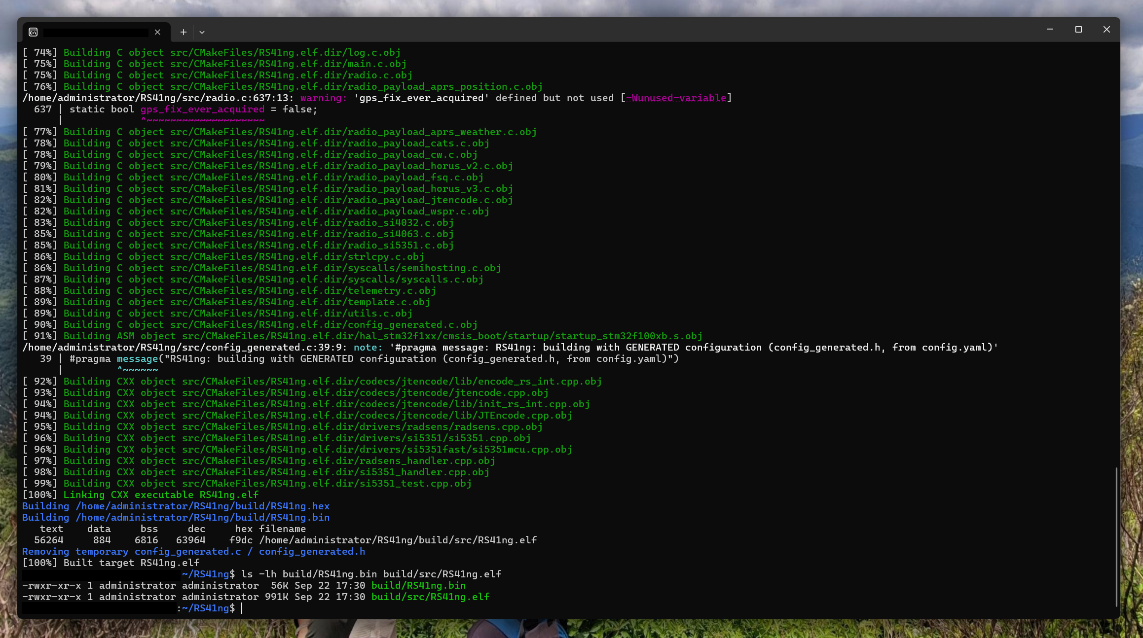
The web configurator’s standard instructions use Docker, but I already had Windows Subsystem for Linux available. I installed the ARM toolchain, CMake, build utilities, OpenOCD, and USB tools in Ubuntu:
sudo apt update
sudo apt install git cmake build-essential gcc-arm-none-eabi \
  libnewlib-arm-none-eabi openocd usbutils
The current configurator uses Bun to convert config.yaml into generated C source. I installed Bun, cloned RS41ng, and copied the downloaded configuration into the repository:
curl -fsSL https://bun.sh/install | bash -s "bun-v1.3.14"
source ~/.bashrc

cd ~
git clone https://github.com/mikaelnousiainen/RS41ng.git
cd RS41ng

cp "/mnt/c/Users/jball/Downloads/config.yaml" ./config.yaml
bun install --frozen-lockfile
bun run scripts/generate_config.ts config.yaml
The generator created:
src/config_generated.h
src/config_generated.c
I then built the DFM-17 target:
mkdir -p build
cd build
cmake -DCMAKE_TOOLCHAIN_FILE=../cmake/arm-none-eabi-gcc.cmake \
  -DDFM17=1 ..
make -j$(nproc)
The resulting binary was 57,148 bytes:
/home/administrator/RS41ng/build/RS41ng.binI copied it to Windows with a descriptive filename and verified that the source and destination hashes matched:
cp ~/RS41ng/build/RS41ng.bin \
  /mnt/c/Users/jball/Downloads/RS41ng-KN4OLA-12.bin

sha256sum ~/RS41ng/build/RS41ng.bin \
  /mnt/c/Users/jball/Downloads/RS41ng-KN4OLA-12.bin
Both copies produced:
97e9d64463be140ad8c06277ced552303f8ce7e49befeaf19e036e846dd49450Why the Browser Flasher Did Not Work
The RS41ng browser flasher detected the ST-LINK/V2 but failed before reaching the target:
Connect failed: Offset is outside the bounds of the DataViewThat error occurred in both Edge and Chrome. It appeared to be a WebUSB/ST-LINK parsing problem rather than a DFM-17 problem, so I stopped using the browser flasher and moved to native tools.
Forwarding the ST-LINK into WSL
For OpenOCD testing, I installed usbipd-win. Windows identified the ST-LINK as VID:PID 0483:3748 on bus ID 2-10.
usbipd list
usbipd bind --busid 2-10
usbipd attach --wsl --busid 2-10
WSL then saw:
Bus 001 Device 002: ID 0483:3748 STMicroelectronics ST-LINK/V2OpenOCD detected the programmer but could not attach to the STM32, even at 100 kHz and in connect-under-reset mode:
sudo openocd \
  -f interface/stlink.cfg \
  -f target/stm32f1x.cfg \
  -c "adapter speed 100; reset_config srst_only srst_nogate connect_assert_srst; init; reset halt; shutdown"
Error: init mode failed (unable to connect to the target)Moving to STM32CubeProgrammer
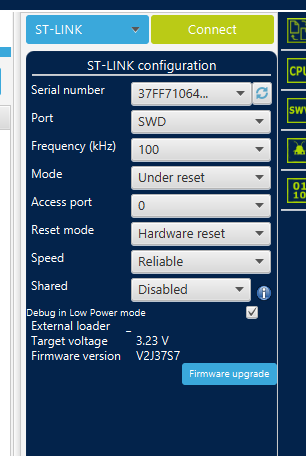
I detached the programmer from WSL and installed STMicroelectronics’ STM32CubeProgrammer for Windows.
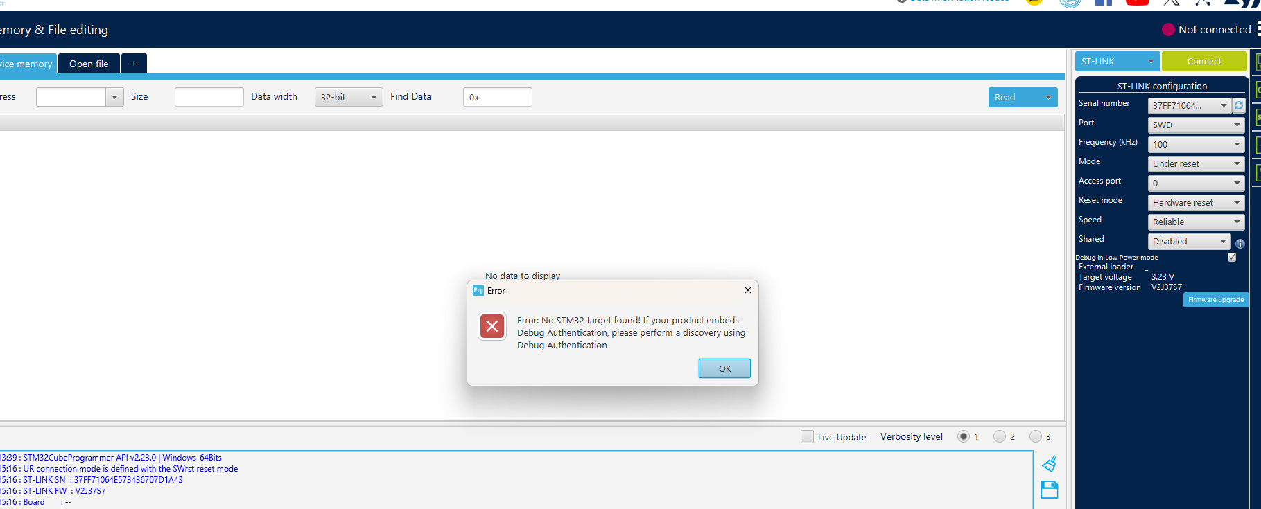
CubeProgrammer saw the ST-LINK, its serial number, firmware V2J37S7, and approximately 3.27 volts. However, both normal SWD and automatic under-reset connections failed:
Error: Unable to get core ID
Error: No STM32 target found!
The radio provided an important clue: clicking Connect immediately interrupted the original 404.000 MHz transmission. That proved the red reset wire was reaching the DFM-17 and affecting the processor. The reset path was working electrically, but the debugger still could not establish an SWD session.
Why Automatic Reset Failed
We (myself and the AI overlords) did not reverse-engineer the ST-LINK clone’s reset driver, so the exact internal failure remains unproven. The evidence supports a reset-timing problem rather than a wiring problem:
- Continuity from the ST-LINK breakout to STM32 NRST was correct.
- Asserting reset stopped the factory transmission and produced an audible interruption on the receiver.
- Automatic connect-under-reset still failed to obtain the ARM core ID.
- Holding nRESET physically low and releasing it after the connection attempt began worked immediately.
The likely explanation is that the ST-LINK-compatible dongle was pulsing or releasing nRESET before its 5 kHz SWD session was synchronized. The DFM-17’s original firmware could then resume quickly enough to close the useful connection window—possibly by reconfiguring debug pins, entering its normal power-control sequence, or otherwise moving beyond the reset state expected by the debugger.
The manual method replaced uncertain programmer timing with a deterministic sequence: hold the MCU in hardware reset, begin the SWD connection, and then release reset while the programmer is actively waiting.
The Manual-Reset Breakthrough
I disconnected the red wire from the ST-LINK’s RST output but left its other end connected to DFM-17 nRESET. I then placed the loose end on ground, which held the STM32 in reset.
With the DFM power button held to maintain battery power, I started STM32CubeProgrammer at the slowest SWD rate. About one second after pressing Enter, I removed the red wire from ground while continuing to hold the DFM power button:
& "C:\Program Files\STMicroelectronics\STM32Cube\STM32CubeProgrammer\bin\STM32_Programmer_CLI.exe" `
  -c port=SWD freq=5 mode=UR reset=HWrst
For the first time, the STM32 answered:
SWD freq    : 5 KHz
Connect mode: Under Reset
Reset mode  : Hardware reset
Device ID   : 0x420
Revision ID : Rev Z
Device name : STM32F100 Low/Medium density Value Line
NVM size    : 64 KBytes
Device CPU  : Cortex-M3
That was the breakthrough. The soldering, ribbon orientation, SWDIO, SWCLK, ground, reset, battery power, programmer, and target MCU were all confirmed.
Mass Erase, Program, and Verify
I repeated the manual-reset sequence with the destructive programming command. At this point I understood that a successful mass erase would permanently remove the factory firmware.
& "C:\Program Files\STMicroelectronics\STM32Cube\STM32CubeProgrammer\bin\STM32_Programmer_CLI.exe" `
  -c port=SWD freq=5 mode=UR reset=HWrst `
  -e all `
  -d "C:\Users\jball\Downloads\RS41ng-KN4OLA-12.bin" 0x08000000 `
  -v
The result:
Mass erase successfully achieved

File download complete

Download verified successfully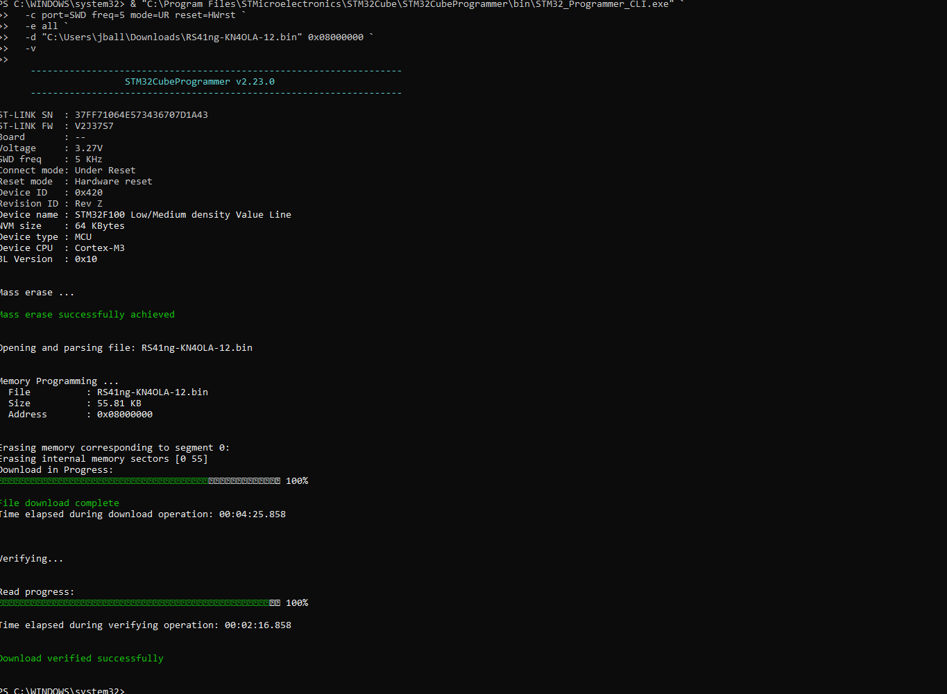
First Boot
After programming, I removed power, restored the red wire to the ST-LINK RST pin, disconnected the programming cable, attached the DFM antenna, and reinstalled the batteries.
The factory signal on 404.000 MHz was gone. The DFM-17 came alive on approximately 432.501 MHz with the new Horus V3 transmission pattern. The onboard LEDs also behaved according to the RS41ng configuration: green for GPS status and red during transmission.
Because the configured RF value represents the lower Horus tone, an SSB receiver would normally be tuned about 1 kHz below it—approximately 432.500 MHz USB—to place the four tones in the audio passband. An FM-only radio can confirm the presence of RF but is not the preferred source for Horus decoding.
Receiving Horus V3 and SondeHub Amateur
Horus Binary V3 is 4FSK telemetry, not APRS. An APRS TNC, digipeater, or ordinary FM radio will not decode it directly. The recommended receiving chain is:
DFM-17 → 432.501 MHz RF → RTL-SDR or SSB receiver → Horus decoder → SondeHub AmateurWebHorus can accept audio or directly control an RTL-SDR in a Chromium-based browser. For launch-day reliability, Horus-GUI is the stronger primary decoder.
Once a receiving station successfully decodes the packets and enables uploading, KN4OLA-12 can appear on SondeHub Amateur. The transmitter itself has no Internet connection; the receiving station performs the upload.
Lessons Learned
- Continuity beats confidence. A keyed cable and matching photograph still produced a completely reversed mapping. I’ll admit, this was frustrating.
- Test to the MCU, not merely to the connector. Verifying PA13, PA14, NRST, and VSS removed ambiguity from the hardware diagnosis. Mapping the connectivity with my Klein CL700 to the actual pin on the microchip restored confidence that I hadn’t screwed the soldering job.
- A reset response does not prove a successful debug connection. The DFM
- Manual reset is a legitimate recovery technique. Holding nRESET low and releasing it after the connection began turned repeated failures into an immediate core-ID response.
- Hash the firmware before destructive work. Once factory flash is erased, “I think this is the right binary” is not a troubleshooting strategy.
- Keep independent tracking paths. A Horus receiver and an APRS receiver should not compete for a single RTL-SDR on launch day.
Final Result
The recovered Graw DFM-17 is now a purpose-built amateur-radio balloon tracker running RS41ng, transmitting Horus Binary V3 as KN4OLA-12 on 432.501 MHz. It retains the DFM-17’s onboard GPS and radio hardware while adding a modern, weak-signal-capable telemetry format, additional DFM telemetry, and battery-conserving landed mode.
The project was a reminder that successful embedded work rarely comes from one magic command. It comes from reducing uncertainty one measurement at a time: confirm power, confirm pin numbering, confirm continuity, confirm reset behavior, confirm processor identity, verify the binary, and only then erase and write.
And, yes, the soldering held up just fine.
References
- RS41ng on GitHub
- RS41ng Web Configurator
- Project Horus GUI
- HorusDemodLib
- WebHorus
- SondeHub Amateur
- STM32CubeProgrammer
- usbipd-win
73 de KN4OLA