I have a 2014 F-250 Super Duty 6.7 liter diesel truck that is equipped with four upfitter (auxiliary) switches. These four switches can control a variety of equipment and are rated for higher amperage starting on switch 1 and the lowest amperage on switch 4.
Setup was pretty easy once I finished digging through three websites, Ford’s “Body Builders Layout Book”, and two YouTube videos.
In order to idle to your desired RPM, you will need to install a resistor between wires “SOLID GREEN” and “WHITE/BROWN” on the driver’s side floor near the parking brake lever. There is a white tag with capped wire ends for customer accessories. Once the resistor is in place connect the “SOLID BROWN” auxiliary switch wire to the “YELLOW/GREEN” wire in the accessory bundle. This will enable your high idle when AUX switch 4 is flipped on, truck is in PARK, and the parking brake is ENGAGED.
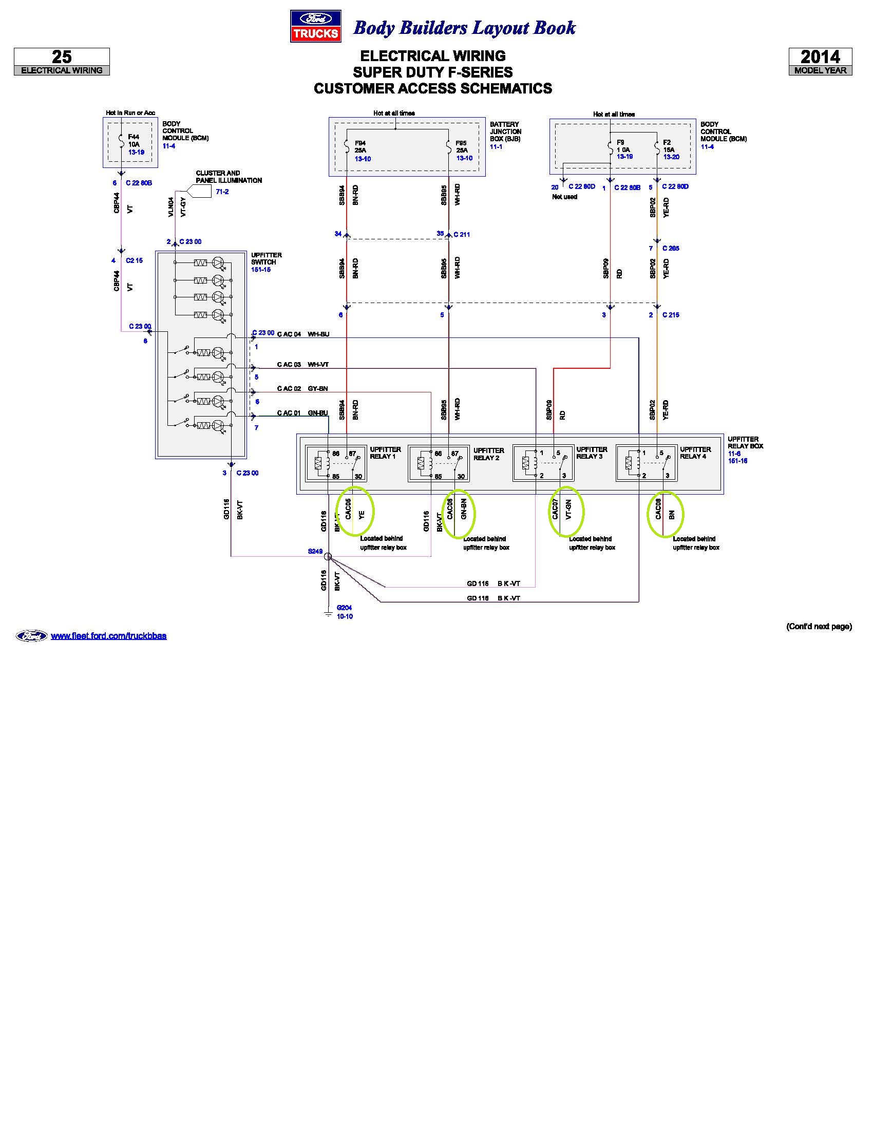 I’ve circled the upfitter switch wire colors on this diagram.
How do you know what resistor controls the idle speed? Easy: read Q-180R2 page 6 table B or if the link is broken, you can download Q-180R2 here: Q-180R2 – 2011 and later F-Super Duty 6.7L Engine Stationary Elevated Idle Control
I picked up these 20K resistors and these 10K resistors on Amazon.
Table B
RPM Ohms Volts
SEIC Mode
900 51000 0.400
1000 36000 0.590
1200 20000 0.971 – 1200 RPMs insert a 20K resistor
1400 12000 1.352 – 1400 RPMs insert a 12K resistor
1600 9100 1.733
1800 6200 2.114
2000 4700 2.495
2200 3300 2.876
2400 2400 3.257
2600 1800 3.638
2800 1100 4.019
3000 680 4.400
This is what you need on the 2014 F-250 6.7L Super Duty:
- A resistor of your choosing. Common resistor options are the 20K resistor. I chose a 10K resistor. See the links above.
- Access to an available auxiliary switch.
- A soldering iron (preferred) or butt-style crimps.
- Shrink tubing and a heat gun (preferred) or electrical tape.
- Post 2 in this thread explains setup in more detail on an older model Ford. https://www.ford-trucks.com/forums/409720-hooking-up-high-idle-w-upfitter-switches.html
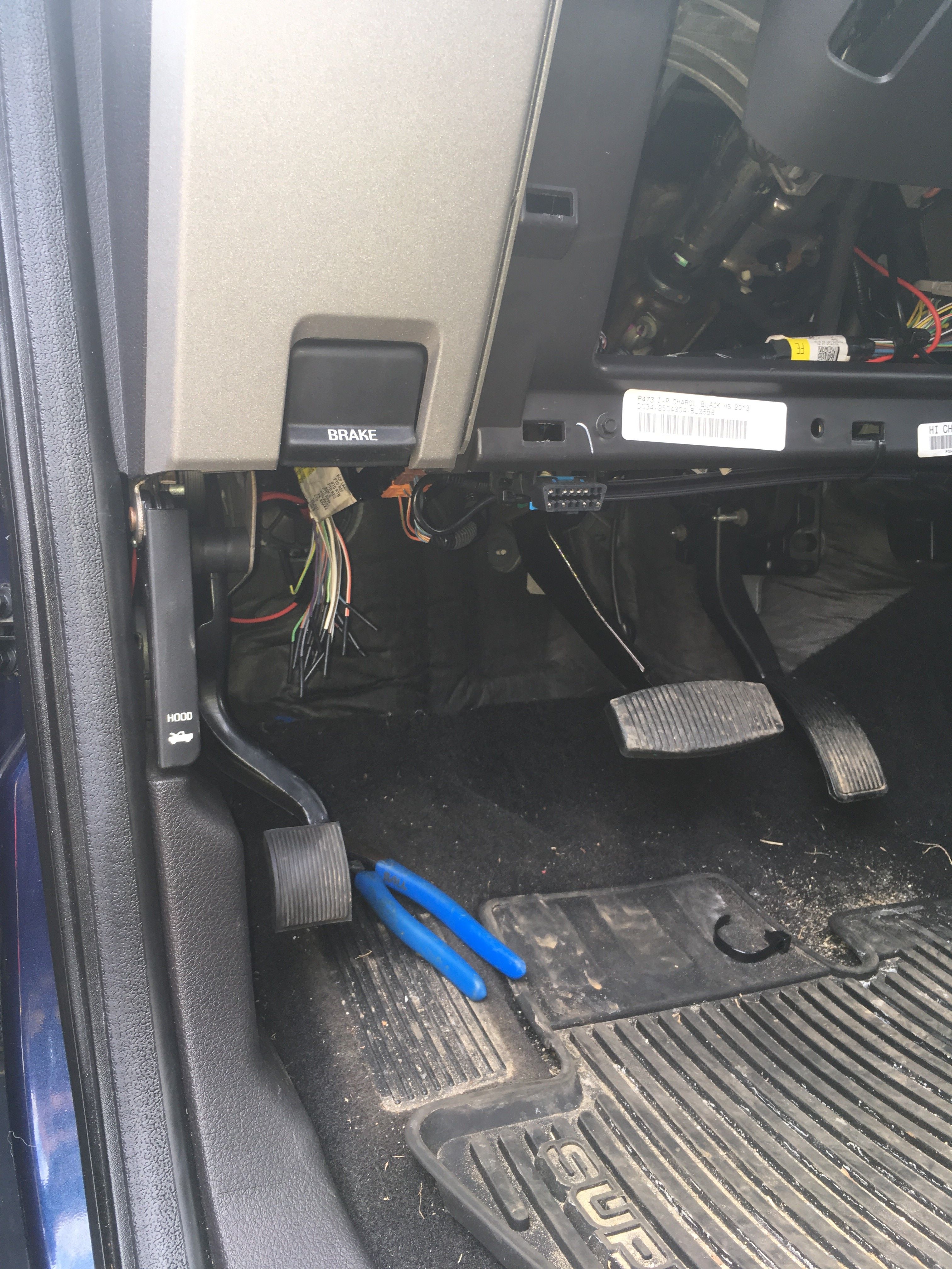 Customer accessory bundle near parking brake release lever.
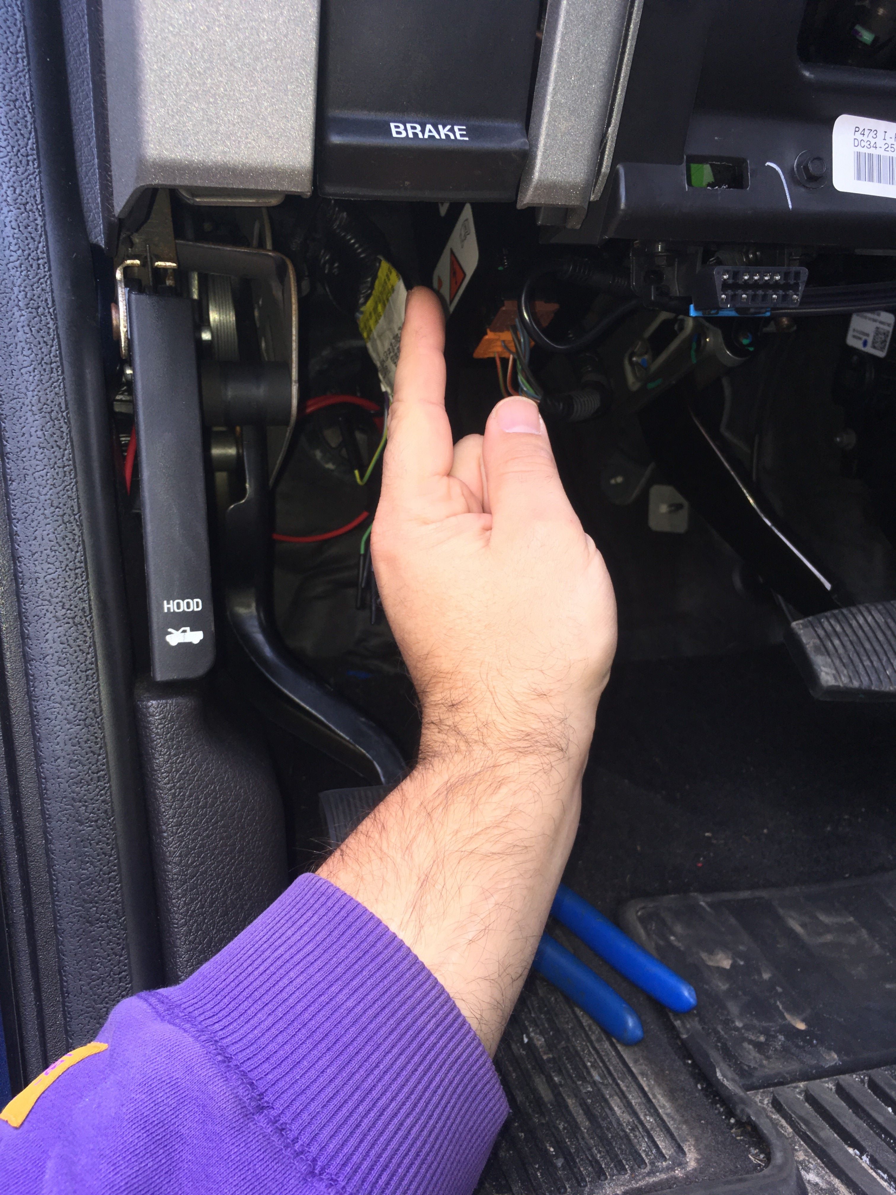 Upfitter switch wires are ABOVE the accessory bundle almost in line with your knee when sitting down. They are folded over and hard to see. Break them loose and give them a little tug.
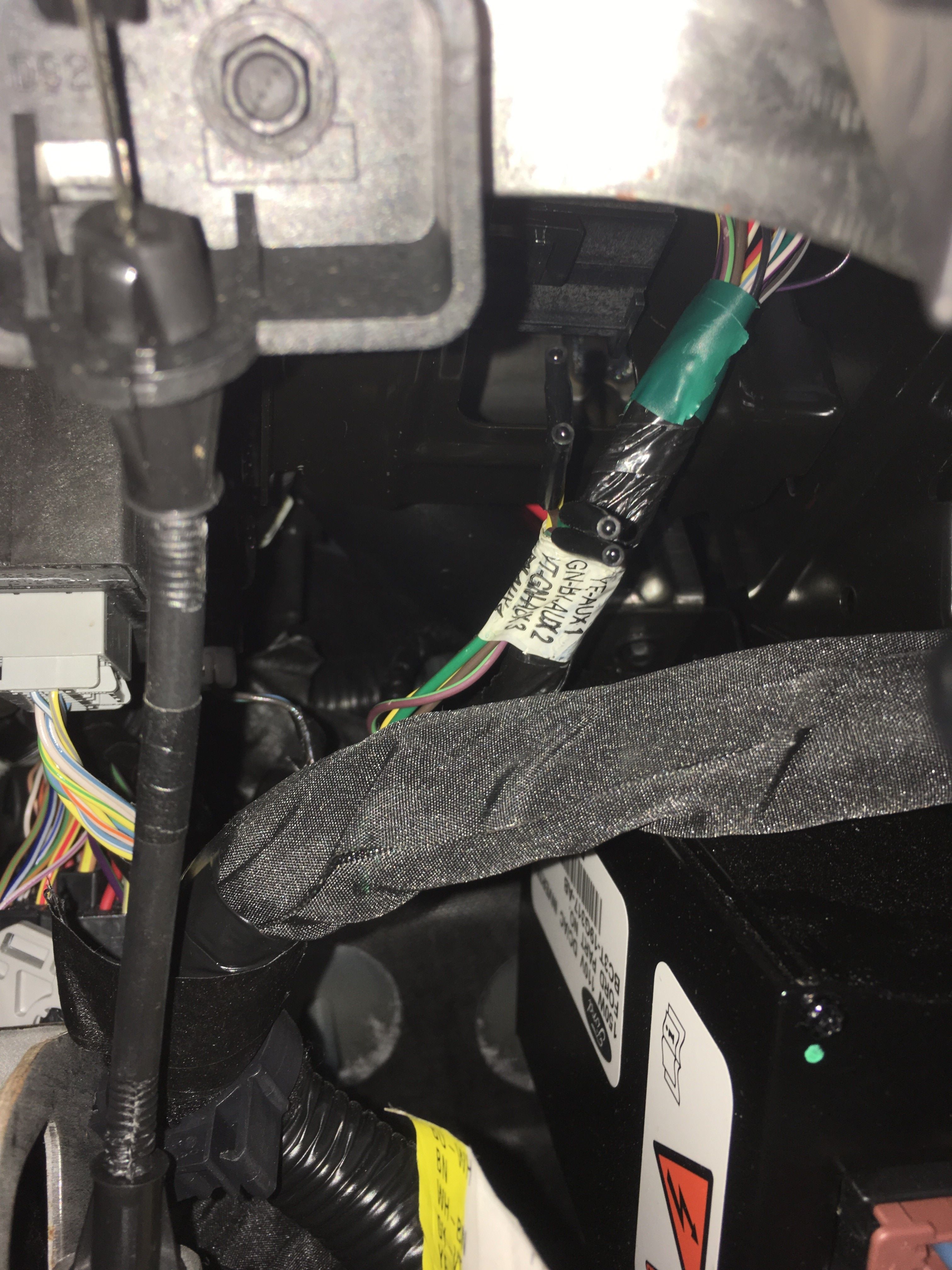 Looking up at the upfitter switch bundle.
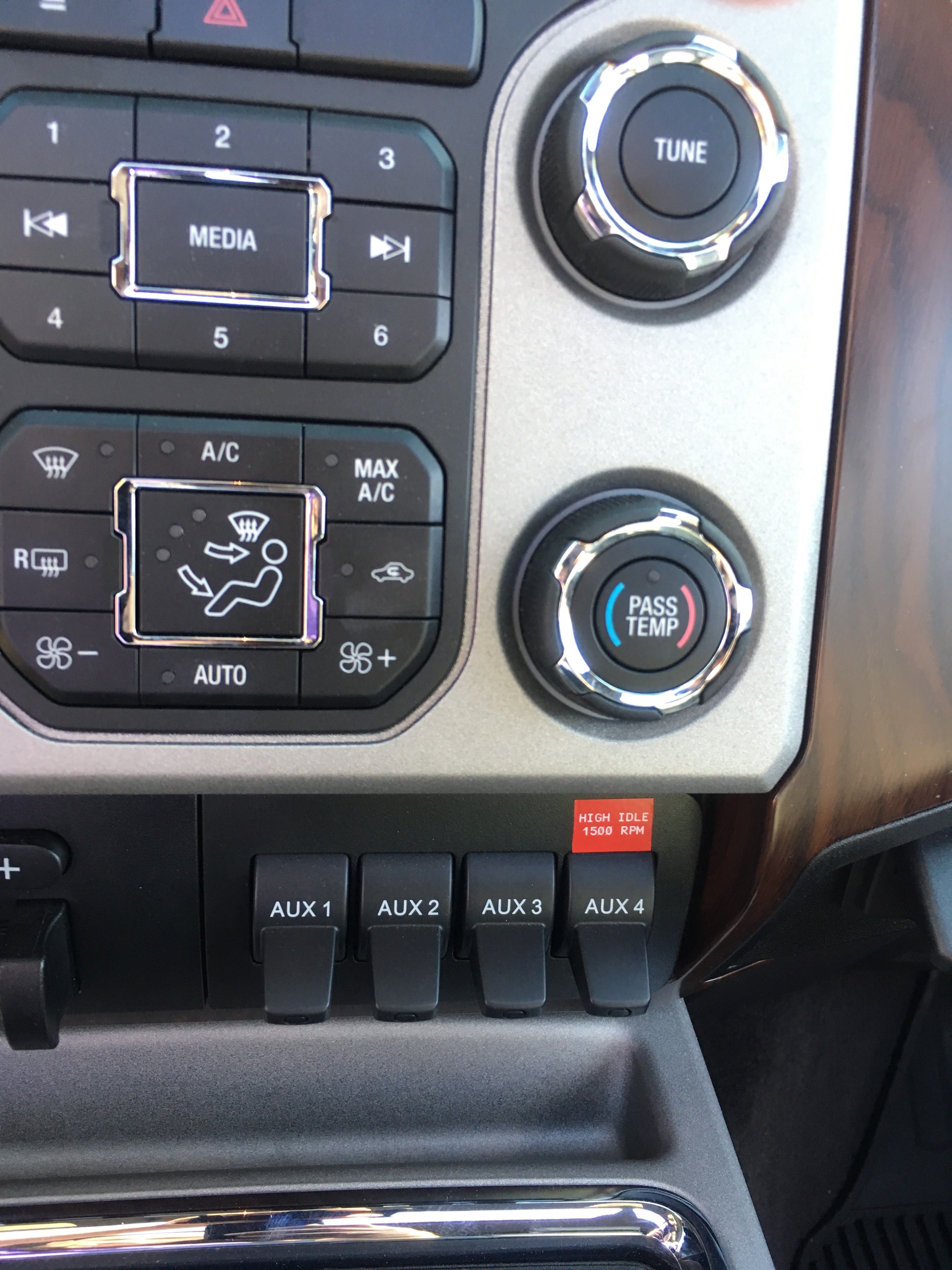 A nice little label so I remember what switch controls the high idle. Also useful when taking the “mobile office” out to the field and somebody else is using the truck.